Common Network Topology Types
There are various types of network topologies that each have their unique purposes. Down below, you will find information about the following types of network topologies: bus, star, mesh, ring, tree, hybrid and point-to-point. In the network diagrams below, the points represent the nodes and the lines represent their connections using cables. Although these are separate types of topologies, different topologies can be combined together. For example, it’s common that the bus and star topologies are mixed together.
Bus Topology


The bus topology consists of having one main cable known as the backbone of the network and all the nodes are directly connected to this cable. When a node wants to communicate with another mode, it delivers a broadcast message to the backbone/cable. The message is sent out on the cable until it reaches its intended recipient. As the bus topology is made out of just on cable, the message will go to every node until it finds the correct recipient. If the device’s address is not the same as the intended address, the device simply ignores the data. However, if the intended address matches the device address, the data will be accepted and processed. Usually, at the end of the cable there are terminators which absorb and stop the signals so that they don’t continue to rebound and continue moving from one end of the cable to the other. There are two types of bus topologies. Linear bus topology is when there is just one line of cable that has to clear endpoints. The disturbed bus topology is when there’s more than one linear pattern in a network and they are all connected together. Typically, the type of wire used is a coaxial or RJ-45 network cable, which are both inexpensive cables.
Star Topology

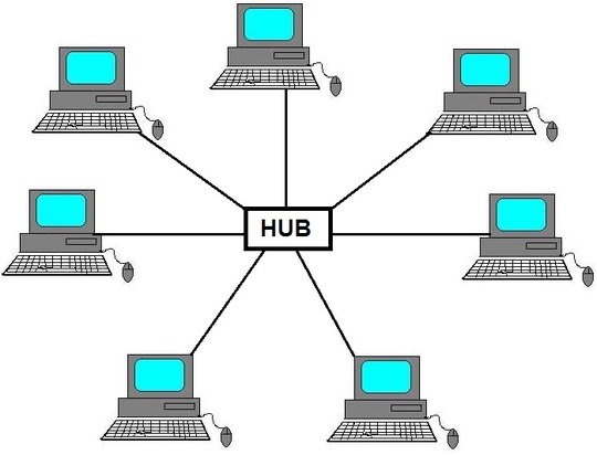
Known as one of the most common topologies, the star topology is when all the nodes are connected to a central server. The central node could be either a hub, switch, router or even a computer. The nodes are connected to the central server device through point-to-point connections. Therefore, it means that the nodes are connected to the central server through a single wire. Technically, the nodes are not connected to each other, however with the help of the hub, they’re connected. The network doesn’t have to look exactly as a star but as long as each node is connected the central server device then it is considered to be star topology. The central server device acts as a repeater since when it receives a signal, it retransfers it somewhere else. For example, the way that messages are transmitted is that say, node A wants to send a message to node B, it will start by sending a signal to the central server device. The central server device will see the address of which the message is addressed to and will transmit that signal to the intended recipient, which in this case in node B. Similar to the bus topology, star topology usually uses coaxial cable or RJ-45 network cable, which as I said before are quite low-priced cables.
Mesh Topology

Mesh topology is when the nodes are connected with each other. This type of topology is often used wirelessly since if you used it using cables, there would be a large amount of cables required. There are two ways that the mesh topology operates: routing or flooding. In routing, the signals are sent out on a predefined path based on the routing logic. The paths that the devices create can vary. Some examples include: directing the signals to the route that takes that’s the shortest distance or creating a route to avoid the broken links. Flooding, which is the simpler way to operate the mesh topology is when the signals are sent to all of the nodes until the device with the corresponding address accepts it. This works due to the time to live (TTL), which gives the signals a fixed number of time they’re allowed to go around the mesh before they’re removed. There are two types of mesh topology: full and partial. Full mesh topology is when each node is individually connected to every other. If we want to calculate the amount of connections in total in the network we can use the formula: n(n-1)/2 (n= number of nodes in the network). Meanwhile, partial mesh topology is when some nodes are connected in the full mesh style while the others are connected to only one or to other nodes. The reason why we do this, is since it’s an inexpensive way to have redundancy (reliability) in the network without having the full mesh, which tends to cost more but is more reliable.
Ring Topology


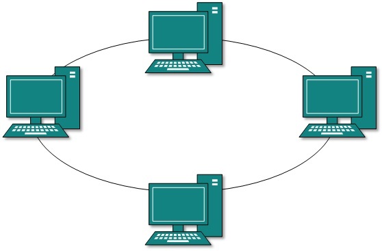
In ring topology, the nodes are connected in a circular form. Each node is connected to two other nodes, one in the front and one behind, forming one closed continuous route for signals to be transmitted. The message being transmitted travels around the ring, so it goes past every node. This kind of topologies can be found in certain office buildings or school campuses. When there is a large amount of nodes in the network, repeaters are used a lot because repeaters are able to replicate a signal and when there’s a lot of nodes, there’s a big chance that the signal will have to travel very far to reach the destination. Therefore, data can be lost while transmitting the signals across so many nodes. However, with repeaters, since they’re able to replicate signals, they can regenerate a signal if it is ever messed up while being transmitted. There are two kinds of ring topologies: unidirectional and bidirectional. A unidirectional ring topology is when the signals are transmitted in only one direction, either clockwise or counterclockwise. As you probably guessed, bidirectional ring topology is when the signals can be transmitted in both ways. This is possible due to dual ring topology. In dual ring topology, there are two ring networks and the secondary topology usually serves as a backup incase the first stops working. The direction which the signals flow is the opposite for the two ring networks. Something common that happens with ring topologies is token passing. A token is basically something that a every node needs in order to be able to release information onto the network. The token is passed around the ring to each node. When the node has a token and if they have information to release to the network they may do so. However, if they do not want to release any information they can simply pass on the token to the next node. The token is passed around the entire route and the nodes may only release information onto the network when they have the network. If the node does not have the token they have to wait until it reaches them. Typically, coaxial cable or a RJ-45 network cable are used.
Tree Topology

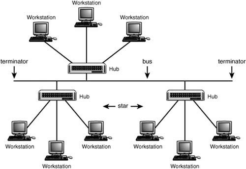
The tree topology is actually a hybrid. Basically, the tree topology is a combination of the bus and star topology. As we know already, the bus topology consists of a main cable known as the backbone and all the nodes attach to this. The star topology works by having one central server device which all the nodes are connected to. Therefore, when we combine the two and make the tree, it works by taking the bus topology and removing the nodes connected to it. Therefore, all that is left is the main cable. To make it the tree, we attach stars to the main cable. The way that we connect the stars with the main cable is by connecting the central server device of each star onto the cable.
Hybrid Topology

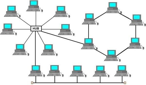
A hybrid is when two or more types of topologies are mixed together. An example, of a hybrid topology is the tree topology since it’s a mix of the star and bus topologies. The hybrid can be mix of any of the following types of topologies: bus, mesh, ring, star, or tree topology.
Point-to-Point Topology

The point-to-point topology is the simplest one. This type of topology is made when we directly connect two nodes using a cable. Not only is this type of topology used in computer networks but it is widely used in telecommunication. When talking about point-to-point in telecommunication, it refers to the connection between two nodes or endpoints. An example of that would be a telephone, since the telephones are connected with each other.